Introduction#
This documentation is designed for those working on projects planning to intergrate with the railway control system as well as those just wanting to find out how the system works in more detail.
Our documentation is currently a work in progress. Please bear us while we get it up to standard. Thanks for your patience.
The Sidings Media Team
Terminology#
The key words “MUST”, “MUST NOT”, “REQUIRED”, “SHALL”, “SHALL NOT”, “SHOULD”, “SHOULD NOT”, “RECOMMENDED”, “MAY”, and “OPTIONAL” in this document are to be interpreted as described in RFC 2119.
Symbols#
Diagrams#
The following symbols are used in diagrams relating to the railway control system.
Note
The text inside a shape is used to provide more detail on it’s purpose.
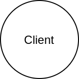
Fig. 1 Symbol for client#
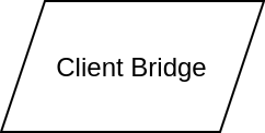
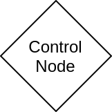
Fig. 3 Symbol for control node#
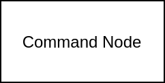
Fig. 4 Symbol for command node#
Fig. 5 Symbol for board interconnects#